Electronic – half-bridge circuit not working, high side running hot Rectifier circuit waveform input Half bridge impedance matching
Powering the Isolated Side of Your Half-Bridge Configuration | Analog
Smps half bridge ir2153 2.0 Basic types of half-bridge single-phase nbdcs with auxiliary circuit Mpq6614-aec1 35v, h-bridge dc motor driver, aec-q100
300w half-bridge smps with uc3825 output voltage problem
Half wave bridge rectifier circuit diagramHalf bridge smps circuit diagram Solved the half-bridge circuit system, applied the tensionMy new half bridge sstc design.
Solved 2. a half-bridge circuit is shown in fig. 1. here,Half-bridge circuit configuration. Circuit diagram of half-bridge (hb) and full-bridge (fb) submodules (smHalf infineon diagramm sstc gdt ics.

Smps ir2153 document
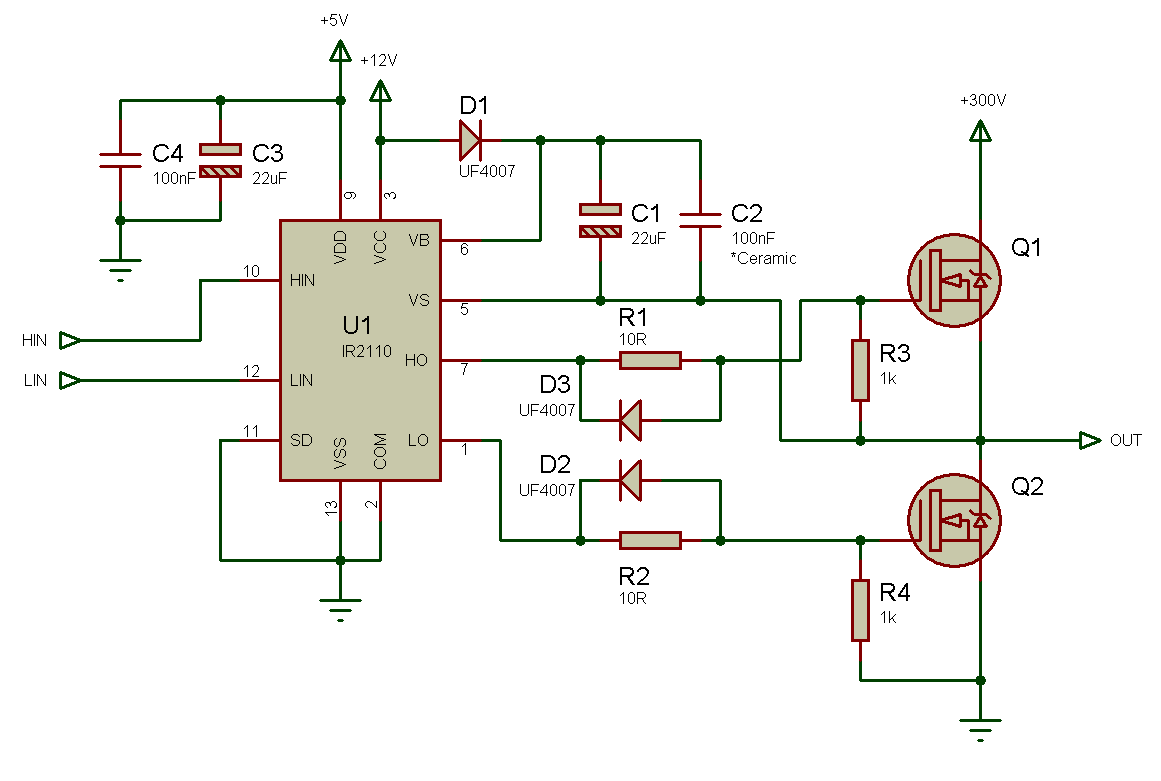
Powering the isolated side of a half-bridge configurationSchematic diagram of half bridge converter circuit Powering the isolated side of your half-bridge configurationHalf-bridge schematic.
Half bridge smps circuit diagramCircuit diagrams of single-phase (a) h-bridge and (b) half-bridge Bridge configuration inductance sic interconnection overvoltage pcbPrincipal circuit diagram of a half bridge..

Schematics of the electrical characterization of the half-bridge
Medievale mormorio tentazione h bridge mosfet inverter ingrandimento(a) conceptual diagram of a power system using a half-bridge circuit to Half bridge method with different versions of the techniques used smpsHalf bridge smps circuit diagram.
A half-bridge circuit is shown in fig. 1. here,Rectifier circuit diagram Half bridge type ii circuit diagram in fig. 15, r 1 and r 2 are theEquivalent circuit for the bottom side of the half-bridge module (gate.

Half bridge configuration.
Half wave bridge rectifier circuit diagramSwitched mode power supply H-bridge transistor circuitHalf wave bridge rectifier circuit diagram.
Half‐bridge circuit and its average model .


Equivalent circuit for the bottom side of the half-bridge module (gate

Half Bridge Impedance Matching - Electrical Engineering Stack Exchange

Powering the Isolated Side Of A Half-bridge Configuration | Electronic
Half Bridge Smps Circuit Diagram

Half Bridge Type II Circuit Diagram In Fig. 15, R 1 and R 2 are the

Half Wave Bridge Rectifier Circuit Diagram

Electronic – Half-bridge circuit not working, high side running hot

MPQ6614-AEC1 35V, H-Bridge DC Motor Driver, AEC-Q100